VN-Link vs VN-Tag
VNTag is needed to augment the forwarding capability of an Ethernet switch and make it capable to operate in a virtualized environment. Classical Ethernet switches do not support the forwarding of frames where the source and destination MAC address are on the same port and therefore do not support forwarding frames between two VMs connected on the same switch port. VNTag solves this and other issues by creating a virtual Ethernet interface per each VM on the switch. Since the switch is capable of forwarding between these virtual Ethernet interfaces, it is capable of forwarding between VMs connected on the same physical port.
Most important fields in VN-Tag is the dvif_id and svif_id. Dvif_id is a 12-bit value mapped to a single host interface to which an Ethernet frame will be forwarded. Svif_id is a 12-bit value mapped to the host interface that received this frame (if it is going from the FEX to the parent switch).
When an Ethernet frame is received on a host interface, The Fabric Extender adds a VNtag to the frame and forwards it to one of the fabric interfaces. The parent switch recognizes the logical interface that sent the frame (through the Svif_id field), removes the tag, and forwards it according to its MAC address table.
In the other direction (parent switch receives a frame that is destined to a FEX host interface), The parent switch reads the frame destination MAC address and forwards it to a logical interface index in its MAC address table. The switch inserts the VNtag associated with the logical interface and forwards it to the correct FEX. Receiving this frame, the FEX recognizes the associated VIF (through the Dvif_id), removes the VNTag, and sends it to the mapped host interface. From a data plane perspective, forwarding in Fabric Extender host interfaces completely depends on the parent switch. Consequently, a frame exchange between two host interfaces always traverses the parent switch, even if they are located in the same Fabric Extender.
Cisco has been shipping VNTag as a prestandard port extension protocol since 2009 in our well known FEX devices. As you know from previous article VNTag solution is prestandard for 802.1Qbh which was renamed to 802.1BR.
Now whats the deal with VN-Link? To know how VN-Link relates to VNTag first look how the FEX design looks like. In the picture below you see FEX with his parent switch. The physical link between parent switch and fabric extender is called Fabric Interface (FIF). The physical ports on the FEX where the actual hosts are connected are called Host Interfaces (HIF). In the parent switch new virtual ports are created that are called the Logical Interfaces (LIF). This is a data structure in the parent switch that emulates an Ethernet interface. It carries properties such as VLAN membership, access control list (ACL) labels, and STP states and is mapped to a virtual interface created on a Fabric Extender. These logical interfaces are mapped to virtual ports in the FEX called Virtual Interfaces (VIF). VIF is a logical entity inside Fabric Extenders that receives its configuration from the parent switch, and it is used to map frames to a switch Logical Interface (LIF). When one VIF wants to communicate with other VIF on same FEX it must go through the parent switch.
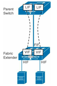
The mapping between a parent switch LIF and a Fabric Extender VIF is called a Virtual Network Link (VN-Link), and it is defined through a special tag that is inserted on all Ethernet frames that traverse these physical links. This extra header is called a Virtual Network Tag (VNTag), and its main objective is to differentiate frames received from (or sent to) distinct FEX host interfaces.
Cisco VN-Link
Cisco is using the DVS framework to deliver a portfolio of networking solutions that can operate directly within the distributed hypervisor layer and offer a feature set and operational model that are familiar and consistent with other Cisco networking products. This approach provides an end-to-end network solution to meet the new requirements created by server virtualization. Specifically, it introduces a new set of features and capabilities that enable virtual machine interfaces to be individually identified, configured, monitored, migrated, and diagnosed in a way that is consistent with the current network operation models.
These features are collectively referred to as Cisco Virtual Network Link (VN-Link). The term literally indicates the creation of a logical link between a vNIC on a virtual machine and a Cisco switch enabled for VN-Link. This mapping is the logical equivalent of using a cable to connect a NIC with a network port of an access-layer switch.
Virtual Ethernet Interfaces
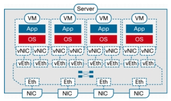
A switch enabled for VN-Link operates on the basis of the concept of virtual Ethernet (vEth) interfaces. These virtual interfaces are dynamically provisioned based on network policies stored in the switch as the result of virtual machine provisioning operations by the hypervisor management layer (for example, VMware vCenter.) These virtual interfaces then maintain network configuration attributes, security, and statistics for a given virtual interface across mobility events. The vEth ports as regular ports seen in the N5K (or in 1000v). You can then configure these vEth ports same like you can configure FEX ports in N5K (or 1000v) to enforce network policy.
Virtual Ethernet interfaces are the virtual equivalent of physical network access ports. A switch enabled for VN-Link can implement several vEth interfaces per physical port, and it creates a mapping between each vEth interface and the corresponding vNIC on the virtual machine. A very important benefit of vEth interfaces is that they can follow vNICs when virtual machines move from one physical server to another. The movement is performed while maintaining the port configuration and state, including NetFlow, port statistics, and any Switched Port Analyzer (SPAN) session. By virtualizing the network access port with vEth interfaces, VN-Link effectively enables transparent mobility of virtual machines across different physical servers and different physical access-layer switches.
Port Profiles
Port profiles are a collection of interface configuration commands that can be dynamically applied at either physical or virtual interfaces. Any changes to a given port profile are propagated immediately to all ports that have been associated with it. A port profile can define a quite sophisticated collection of attributes such as VLAN, private VLAN (PVLAN), ACL, port security, NetFlow collection, rate limiting, QoS marking, and even remote-port mirroring (through Encapsulated Remote SPAN [ERSPAN]) for advanced, per-virtual machine troubleshooting. In the figure below you can see relationship Between Virtual and Physical Network Constructs in a VN-Link Enabled Switch (Cisco Nexus™ 1000V Series Switches)
- As a Cisco DVS running entirely in software within the hypervisor layer (Cisco Nexus 1000V Series
- With a new class of devices that support network interface virtualization (NIV) and eliminate the need for software-based switching within hypervisors
Deploying VN-Link in Existing Networks with the Cisco Nexus 1000V Series
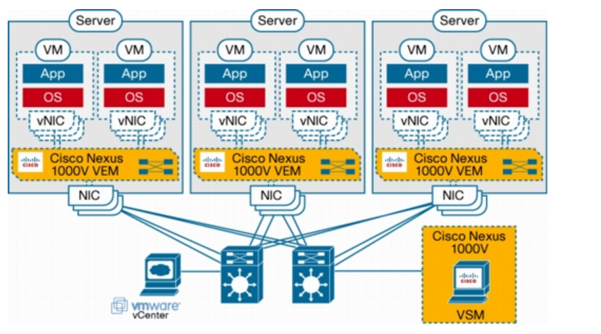
With the introduction of the DVS framework, VMware also allowed third-party networking vendors to provide their own implementations of distributed virtual switches by using the vNetwork switch API interfaces. Cisco and VMware collaborated closely on the design of these APIs, and the Cisco Nexus 1000V Series represents the first example of third-party DVSs that are fully integrated with VMware Virtual Infrastructure, including VMware vCenter for the virtualization administrator. When deployed, the Cisco Nexus 1000V Series not only maintains the virtualization administrator’s regular workflow; it also offloads the vSwitch and port group configuration to the network administrator, reducing network configuration mistakes and helping ensure that consistent network policy is enforced throughout the data center.
The Cisco Nexus 1000V Series consists of two main types of components that can virtually emulate a 66-slot modular Ethernet switch with redundant supervisor functions:
- Virtual Ethernet module (VEM)-data plane: This lightweight software component runs inside the hypervisor. It enables advanced networking and security features, performs switching between directly attached virtual machines, provides uplink capabilities to the rest of the network, and effectively replaces the vSwitch. Each hypervisor is embedded with one VEM.
- Virtual supervisor module (VSM)-control plane: This standalone, external, physical or virtual appliance is responsible for the configuration, management, monitoring, and diagnostics of the overall Cisco Nexus 1000V Series system (that is, the combination of the VSM itself and all the VEMs it controls) as well as the integration with VMware vCenter. A single VSM can manage up to 64 VEMs. VSMs can be deployed in an active-standby model, helping ensure high availability.
In the Cisco Nexus 1000V Series, traffic between virtual machines is switched locally at each instance of a VEM. Each VEM is also responsible for interconnecting the local virtual machines with the rest of the network through the upstream access-layer network switch (blade, top-of-rack, end-of-row, etc.). The VSM is responsible for running the control plane protocols and configuring the state of each VEM accordingly, but it never takes part in the actual forwarding of packets.
Deploying VN-Link with Network Interface Virtualization
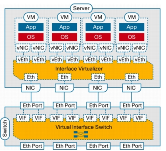
In addition to the distributed virtual switch model, which requires a tight integration between the hypervisor, its management layer, and the virtual networking components and implements switching in software within the hypervisor, Cisco has developed a hardware approach based on the concept of network interface virtualization. NIV completely removes any switching function from the hypervisor and locates it in a hardware network switch physically independent of the server. NIV still requires a component on the host, called the interface virtualizer, that can be implemented either in software within the hypervisor or in hardware within an interface virtualizer-capable adapter. The purpose of the interface virtualizer is twofold:
- For traffic going from the server to the network, the interface virtualizer identifies the source vNIC and explicitly tags each of the packets generated by that vNIC with a unique tag, also known as a virtual network tag (VNTag).
- For traffic received from the network, the interface virtualizer removes the VNTag and directs the packet to the specified vNIC.
The interface virtualizer never performs any local switching between virtual machines. The switching process is completely decoupled from the hypervisor, which brings networking of virtual machines to feature parity with networking of physical devices.
Switching is always performed by the network switch to which the interface virtualizer connects, which in this case is called the virtual interface switch (VIS) to indicate its capability not only to switch between physical ports, but also between virtual interfaces (VIFs) corresponding to vNICs that are remote from the switch. Said in a different way, each vNIC in a virtual machine will correspond to a VIF in the VIS, and any switching or policy enforcement function will be performed within the VIS and not in the hypervisor. The VIS can be any kind of access-layer switch in the network (a blade, top-of-rack, or end-of-row switch) as long as it supports NIV
In addition, a VIS must be enabled to potentially forward a frame back on the same inbound port from which it was received. The IEEE 801.D standard that defines the operation of Layer 2 Ethernet switches clearly states that a compliant switch is never allowed to forward any frames back on the same interface from which they were received. This measure was originally introduced in the standard to avoid the creation of loops in Layer 2 topologies while enabling relatively simple hardware implementations of Layer 2 forwarding engines. The technology that is currently available for implementing forwarding engines allows much more sophisticated algorithms, and thus this requirement no longer needs to be imposed. Nonetheless, the capability of a network switch to send packets back on the same interface from which they were received still requires the proper level of standardization. Cisco defined a protocol, VNTag, that has been submitted to the IEEE 802.3 task force for standardization.
NIV represents innovation at Layer 2 that is designed for deployment within the VN-Link operating framework. Specifically, it includes the same mechanisms, such as port profiles, vEth interfaces, support for virtual machine mobility, a consistent network deployment and operating model, and integration with hypervisor managers, as the Cisco Nexus 1000V Series.
VN-Link and the UCS
An alternative approach is to replace the switch inside the hypervisor with a Port Extender capable of supporting the VNTag/VN-Link architecture. In this case, either the Nexus 5000 switch or the UCS 6100 Fabric Interconnect operates as a controlling bridge VNTag between the Port Extender in the server and the Nexus 5000/UCS 6100. The Port Extender is in charge of tagging the frames leaving the VM and this can happen in one of two ways:
- Inserting the VNTag in the hypervisor software switch (either the Nexus 1000V or the VMware® switch) and then forward the packet to the Nexus 5000/UCS 6100, or
- Having an SR-IOV NIC capable of adding VNTag in hardware. This second approach is clearly superior from the performance perspective, since it does not consume CPU resources in the hypervisor and can potentially enable hypervisor bypass.
The external behavior and benefits are the same as using VN-Link on the Nexus 1000V; however, with the Nexus 5000, all the Ethernet features (switching, ACLs, ERSPAN, QoS, etc.) are performed completely in hardware at wire rate. Network Policies are still defined in terms of Port Profiles. All VMotion/DRS and VN-Link features are also supported.
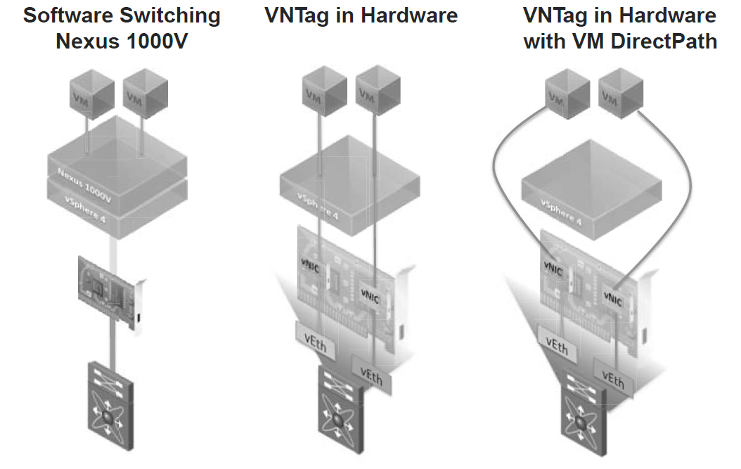
Figure illustrates three different possibilities, from left to right:
- The Nexus 1000V solution described in the previous section: The Nexus 1000V does software switching and applies all the Ethernet features, by using the server processor.
- VNTag in hardware without hypervisor bypass: Each vNIC is mapped to a vEth, the vNIC supports SR-IOV, the switch (Nexus 5000/UCS 6100) applies all the Ethernet features in hardware. This can be achieved without touching the VM and it supports all the VMware features. This feature is supported, for example, in Cisco Palo.
- VNTag in hardware with hypervisor bypass: This is similar to the previous solution, but the hypervisor is completely bypassed for higher performance. VMDirectPath allows VMware® vSphere/ESX® to bypass the hypervisor and map the physical NICs directly to the virtual machines. It currently requires an additional driver in the VM and it does not support VMotion (this limitation will be removed in a future release of vSphere).
VM-Fex
As you have learned in this chapter, Nexus 1000V offers the abstraction of an NX-OS switch in server virtualization environments, providing the same level of control and visibility to virtual machine traffic. Bridging again the chasm between physical and virtual worlds, Cisco has pioneered yet another virtual networking technology: Virtual Machine Fabric Extender (VM-FEX). In essence, VM-FEX emulates a Fabric Extender inside a virtualized host, providing connectivity to its virtual machines. If you remember the concepts with Fabric Extenders a Fabric Extender is a device that acts as a remote linecard for a parent switch, extending a virtualized chassis to multiple server racks while reducing the number of management points in the data center. Mimicking its physical counterparts, VM-FEX consolidates the networking infrastructure, enabling configuration, management, and monitoring of virtual and physical connectivity in the same device. With VM-FEX deployed on a server virtualization environment:
- Each virtual machine has a dedicated virtual Ethernet interface on the parent switch.
- All virtual machine traffic is sent straight to this interface on the parent switch.
- Software-based switching can be eliminated because the parent switch will handle all VM-related traffic.
Cisco virtualized interface cards (VIC) are an integral part of the VM-FEX architecture. Besides creating virtual PCIe I/O devices, these adapters enable the deployment of VNTags in hardware, allowing a parent switch to recognize Ethernet frames from distinct virtual machines. Although single-root I/O virtualization (SR-IOV) embodies a similar principle (the creation of virtual PCIe I/O devices), a Cisco VIC creates fully functional unique and independent PCIe adapters (such as network interface cards [NICs] and host bus adapters [HBAs]) that do not rely on special feature support from operating systems or hypervisors.
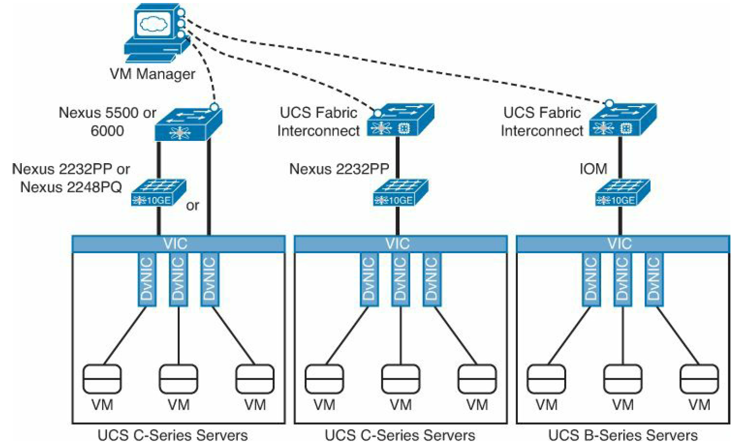
There are several options to implement VM-FEX with Cisco Data Center products. At the time of this writing, the following hardware combinations are supported:
- Nexus 5500 or 6000 switches with UCS C-Series servers equipped with VIC adapters (directly connected or through a Fabric Extender [Nexus 2232PP or 2248PQ])
- UCS Fabric Interconnect with UCS C-series servers equipped with VIC adapters, an connected through a Nexus 2232PP Fabric Extender
- UCS Fabric Interconnect with UCS B-series servers equipped with VIC adapters
In picture below you can see the VM-FEX options.
Virtual Ethernet Port Aggregator (VEPA)
VEPA is standard being lead by HP for providing consistent network control and monitoring for Virtual Machines (of any type.) VEPA has been used by the IEEE as the basis for 802.1Qbg ‘Edge Virtual Bridging.’ VEPA comes in two major forms: a standard mode which requires minor software updates to the VEB functionality as well as upstream switch firmware updates, and a multi-channel mode which will require additional intelligence on the upstream switch. VEPA is also called the tagless solution.
Standard Mode
In the standard mode the software upgrade to the VEB in the hypervisor simply forces each VM frame out to the external switch regardless of destination. This causes no change for destination MAC addresses external to the host, but for destinations within the host (another VM in the same VLAN) it forces that traffic to the upstream switch which forwards it back instead of handling it internally, called a hairpin turn.) It’s this hairpin turn that causes the requirement for the upstream switch to have updated firmware, typical STP behavior prevents a switch from forwarding a frame back down the port it was received on. The firmware update allows the negotiation between the physical host and the upstream switch of a VEPA port which then allows this hairpin turn.
VEPA simply forces VM traffic to be handled by an external switch. This allows each VM frame flow to be monitored managed and secured with all of the tools available to the physical switch. This does not provide any type of individual tunnel for the VM, or a configurable switchport but does allow for things like flow statistic gathering, ACL enforcement, etc. Basically we’re just pushing the MAC forwarding decision to the physical switch and allowing that switch to perform whatever functions it has available on each transaction. The drawback here is that we are now performing one ingress and egress for each frame that was previously handled internally. This means that there are bandwidth and latency considerations to be made. Functions like Single Root I/O Virtualization (SR/IOV) and Direct Path I/O can alleviate some of the latency issues when implementing this. Like any technology there are typically trade offs that must be weighed. In this case the added control and functionality should outweigh the bandwidth and latency additions.
Multi-Channel VEPA
Multi-Channel VEPA is an optional enhancement to VEPA that also comes with additional requirements. Multi-Channel VEPA allows a single Ethernet connection (switchport/NIC port) to be divided into multiple independent channels or tunnels. Each channel or tunnel acts as an unique connection to the network. Within the virtual host these channels or tunnels can be assigned to a VM, a VEB, or to a VEB operating with standard VEPA. In order to achieve this goal Multi-Channel VEPA utilizes a tagging mechanism commonly known as Q-in-Q (defined in 802.1ad) which uses a service tag ‘S-Tag’ in addition to the standard 802.1q VLAN tag. This provides the tunneling within a single pipe without effecting the 802.1q VLAN. This method requires Q-in-Q capability within both the NICs and upstream switches which may require hardware changes.