In high level we can say that FC is protocol that replaces SCSI disk cable with a network. The host machine thinks the disk is locally connected with SCSI cable but it is not, the disk is accessed via SAN network through the FC protocol.
So we moved from this
 to this
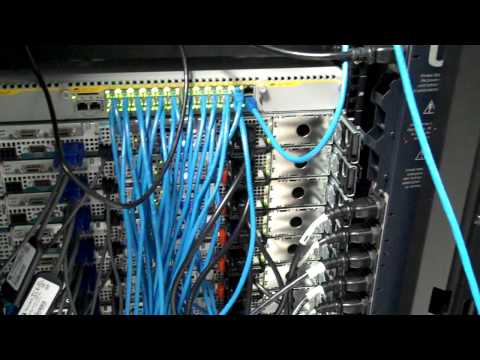
FibreChannel is just protocol stack same like TCP/IP, primarily used to send SCSI commands over the network. In network world we have IEEE standards. In SAN world there is InterNational Comittee for Information Technology Standards (INCITS). For the FC there is explicitly the „T11“ standard. For example for FCoE there is T11 FC-BB-5 standard. However you see there are some standards it is not like in the Network world that network devices more or less operates between each other. Here in SAN world there are lots of issues between different vendors and operability between them. They are using different names to describe same thing, like port types in SAN. So the terminology can be little bit confusing.
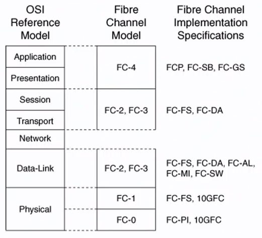
There is one vague model mappings between FC and OSI. FC0-1 is dealing with the physical layer, for example coding/decoding for 1/2/4 gig etc… FC2-4 is for upper layers. For us is most important the FCP (Fiber Channel Protocol) which we can think of this as analogue to TCP. FCP carry our read/write commands over the network. It works same like TCP/IP stack. So when OS wants to write/read something from the disk, the request is sent to HBA. HBA uses FCP to send this commands over the network encapsulating the FCP from UP to Bottom (like in TCP stack)
FC Topologies and Port Types
Topologies
- PointToPoint (FC-P2P) – initiator and target are directly connected. I can imagine this when you for example connect disk to PC with esata port.
- Arbitrated Loop (FC-AL) – this is logical ring topology, similar to Token Ring. Contention is required on the ring. This contention algorithm is called arbitration algorithm. Its similar to CSMD-CD in old ethernet networks with half duplex.
- Switched Fabric (FC-SW) – similar to ethernet switching. Switches are allowing any to any communication without the contention.
Ports
- N_port (Node port) – end host (target and initator) port in P2P and Switched topologies
- NL_port (Node Loop port) – end host (target and initiator) port in AL topology. This difference is because in AL the port must run the AL contention algorithm. Its like we must have half duplex port in hub environment.
- F_port (Fabric port) – the switch port that connects to N_port.
- FL_port (Fabric Loop port) – the switch port that connects to NL_port.
- E_port (Expansion port) – the port between the SAN switches. This is also called Inter Switch Link (ISL). In SAN the ISL is just link between two switches.
- TE_port (Trunk Expansion port) – the port between the switches, which are configured with VSAN functionality. Also called Extended ISL.
- There are other port types like NP, VE, ENode but we will cover these in next sections.
Fibre Channel Addressing
FC addressing is analogous to IP over Ethernet. IP addresses are logical and manually assigned, MAC addresses are physical and burned in.
In FC there are these types of addresses:
- FC WWNs (FC world wide names) – 8 byte burned in physical address in HBA. WWNs are maintain by IEEE. WWN contains the Vendor and company part assigned by IEEE, same like in MAC address. There are more types of WWNs:
- WWNN (Word Wide Node Name). This is end devices physical address (switch, server, HBA). A worldwide node name (WWNN) is a globally unique 64-bit identifier that is assigned to each Fibre Channel node or device. For servers and hosts, WWNN is unique for each HBA (host bus adapter), and in a case of a server with two HBAs, they have two WWNNs. For a SAN switch, the WWNN is a common for the chassis. For storage, the WWNN is common for each controller unit of midrage storage. In case of high-end enterprise storage, the WWNN is unique for the entire array.
- WWPN (World Wide Port Name). This is server, switch, disk, etc… port physical address. A worldwide port number (WWPN) is unique identifier for each FC port of any Fibre Channel device. For server, we have a WWPN for each port of the HBA. For a SAN switch, the WWPN is available for each port in the chassis. For Storage, each host port has an individual WWPN.
- Reason to give to different port different wwpn is same like in ethernet. However why to give address also to the HB, Server or Node (in general) itself? Hmmm maybe we will see.
- NOTE!! WWNs are not used in data plane for switching! The FCIDs are used to switch FC frames. In SAN environment the term switching means routing 😉
- FCID (FC identifier) – 3 byte logical address assigned by fabric. So when HBA port is connected to the network it must go through the connection oriented end-host loging into network process to get the FCID address. FCID is subdivided into 3 subfields:
- Domain ID – each switch gets domain ID. A domain ID is a unique number that identifies the switch or director to a fabric. One byte allows up to 256 possible addresses. Because some of these addresses are reserved, as for the one for broadcast, there are only 239 addresses available. This number means that you can theoretically have as many as 239 switches in your SAN environment. So if node get FCID with Domain ID 1 the other switches knows when they route the traffic to me that I am behind the switch with domain id 1. You can think about this as subnet address in IP world, where routers first route based on subnets and when it reach the directly connected router it check for the physical address in ARP process.
- FC Area ID – groups of ports with same area ID. Used in FC-AL topology, for different loops different area-ids. Not used in Switched topology. But in any case this is something automatically generated, we dont need to configure this.
- Port ID – this is where the end-station is.
- FCID is used in data plane to switch the actual traffic.
- Domain ID can be manually configured otherwise its automatically assigned by Principle Switch. Principle switch is elected by some process where switches are comparing their priorities (like in STP, but this is just election, doesnt influence traffic like STP). No configuration is needed for PS election because it doesnt influence the data plane forwarding like STP does.
Fiber Channel Routing
FC does not use flooding to build a topology like Ethernet does. In Ethernet, the switches build topology in data plane learning source mac addresses when traffic goes through the switch and flooding when there is no destination. In FC there is no such concept. In FC the end node must go through the control plane process – fabric login process.
Fabric Shortest Path First (FSPF) is used to route the traffic between switches. We can think of this as OSPF, it uses the same Djisktras algorithm in background. So when you look into the CLI for same verification, it would be same logic as in OSPF. Node ID in the Shortest Path Tree is the Domain ID. Traffic is then routed via lowest path between Domain IDs. So same logic as in OSPF. Configuration wise there is really not much we can do in FSPF, we can do little tweaking like changing cost of the link in order to do ECMP for example.
NOTE that FSPF runs automatically as a Fabric Service. There is not much to configure.
Fibre Channel Logins
Ethernet networks are connectionless. You just plug in the cable and switches starts learning addresses and you can communicate in L2. In FC it doesnt work like that. FC is connection oriented, you have to ask for permition of Fabric to be allowed to send traffic. The reason for this is that when you plug the HBA into the SAN the HBA doesnt have the FCID to be able to send the traffic. So in case of Ethernet we have our MAC addresses and IP addresses already assigned and our switches are not responsible for giving us the IP address. But in FC we dont have it. We must first register in the control plane of the fabric to be able to send the traffic.
So this is going to be our very fist step when we connect to the fabric to be able to send the traffic, to do the fibre channel logins (FLOGI). Via this process we receive the FCID from the fabric switch. Fiber channel logins has three parts:
- FLOGI (Fabric Login) – this is the most important login part from our point of view. This tells us if both initiator and the target registered into the fabric. N_port tells switch F_port that wants to register to network and start sending traffic. The end node tells the switch here is my WWNN and WWPN. So initially the end node send its WWNN and WWPN and request FCID. The switch then assigns the FCID to the node. You can think about this like DHCP but this service is build into the FC switches. So all switches in the SAN Fabric have to listen for these FLOGIs and provide FCID for both initiator and target. Command to check flogi is show flogi database. When this is done the PLOGI starts.
- PLOGI (Port Login) – this is more related to actual storage array or the HBA. This is end to end login between the nodes. Initiator tells the Target it wants to talk ( i wanna send reads/writes to you). This is usefull for applications to do end to end flow control. So if there is some problem with PLOGI it is actually related to the storage array or HBA and we cannot do much in the network.
- PLRI (Process Login) – this is the upper layer protocol login between the nodes.
- Again the most important from the network point of view will be the FLOGI process.
Fibre Channel Name Server (FCNS)
FCNS is similar to ARP cache. It keeps all the FCID to WWNN/PN mappings. This is very important as the FCIDs are used for the switching and WWNs are used for FLOGI registration process and zoning. In Ethernet the Routers keeps the ARP cache. NOTE that like Principle Switch election or FSPF the FCNS is a distributed fabric service = doesnt need any configuration. So when the end node goes through the FLOGI process and send the WWNN/PN to the switch and receive the FCID, then the end node register itself in the FCNS telling this is the correlation between my WWPN and FCID and if you want to reach me you have to use this FCID. The FCNS also send to the node during the FLOGI process all the relations it has, all the ARP cache so the node can reach everyone.
So this is all build in feature in Fabric and when I am going through the FLOGI process I automatically go through this process and also automatically know how to reach other nodes in the Fabric. The FCNS (show fcns database) is the one of the common command used in fabric. All devices in particular VSAN are able to see each other in FCNS database. All the storage arrays = all the disks are in this FCNS when they are registered. This is very dangerous, thats why zoning was invented. Now we are using the terminology when FCNS send the mapping to end nodes, that he sends the „zoning info“. Because we are restricting what the FCNS send to end nodes, hence we send zoning info.
Note that when you see the mapping WWN to FCID for specific device in the „show fcns database“ the flogi has been successful. This is because if the flogi is not successfull there is no mapping and then it is not in the FCSNS.
Zoning
This is something all switches in fabric must agree on. If some switches will have different zoning configured we can run into the problems. By default all initiators learn about all targets during the FLOGI process. This is what the FCNS is doing, it provides to everyone mapping between the physical and logical address. So its like exchanging the ARP cache in Ethernet with everyone in the topology. This is doing the FCNS, it send the physical to logical address mapping of everyone during the FLOGI process so every can reach everyone.
In LAN world this is not really a problem. If some node talks to other node it doesnt corrupt the network. However in storage world this is problem. If for example the windows server mount the unix partition and write something to it, the whole partition is corrupted. So we need to be very careful. And a way how to prevent this is zoning, where you specify what initiators can talk to what targets. You can think of this as IP ACLs. We specify which WWNs, FCIDs, IPs ( in case of iSCIS) can talk to each other. NOTE like FCNS or FSPF is distributed fabric service propagated automatically to all switches. So for example in ethernet world if the vlan ACLs would not match with vlan ACL in other switch there will be some problems with forwarding the traffic – same analogy is in SAN.
Because creating zoning with WWNs or FCIDs are very difficult (they are in hex), the aliases have been created for this. You then refer to the alias in the zoning rules.
There are two types of zoning. Soft zoning and hard zoning. In soft zoning you restrict what mappings FCNS will send to end nodes during the FLOGI process. This is done just in control plane, so you are restricting what the end nodes can see. They now cannot see everything, you are not going to send the whole WWPN to FCID mapping cache but you are restricting it. However if the end node already know the target he can reach it and manually mount the target he is not able to see, because this zoning is not implemented in data plane. Thats why we have also the hard zoning. In hard zoning, everything is the same like in the soft zoning. The FCNS send restricted zoning info to end nodes, but now this is also enforced in data plane. So if someone wants to map target he is not able to see, he is not able to.
VSAN
Analogy to VLAN/VRF. Traditonally SAN networks were designed as physical separate networks, i.e. SAN islands. Physical separation is costly in terms of CAPEX/OPEX (equipment, power, space, cooling,…). VSANs solve this isolation problem like VLANs solves it in Ethernet. However one of the big differences between VLAN and VSAN is that we dont have any services that are build into the ethernet switches and VLANs. However in SAN there are lots of fabric services build in the switches (FLOGI, FCNS, FSPF, Zoning) so everytime we are creating a VSAN we are creating a copy of Fabric Services (now its similar to VRF). So in case of VSANs they wont be in so big number deployed as are VLANs.
With VSAN the E port now becomes the TE port.
SAN port channeling
Same like in Ethernet we can create port channels between our switches to increase the redundancy. This is much simpler in SAN to create port channel as you just configure the „channel active“ and thats it. The negation protocol is PCP (Port Channel Protocol) similar to LACP.