The terms Unified Fabric or I/O consolidation are synonymous and refer to the ability of a network (both switches and host adapters) to use the same physical infrastructure to carry different types of traffic that typically have different traffic characteristics and handling requirements.
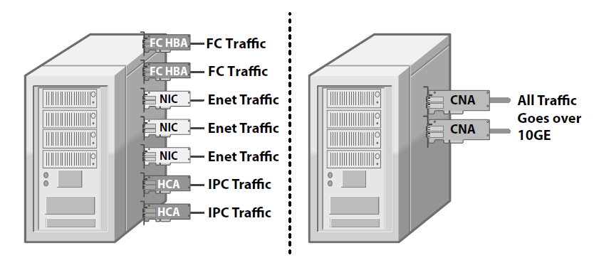
From the network side, this equates in having to install and operate a single network instead of three. From the hosts side, fewer CNAs (Converged Network Adapters) replace and consolidate NICs (Network Interface Cards), HBAs (Host Bus Adapters), and HCAs (Host Channel Adapters). This results in a lower number of PCIe slots required on rack-mounted servers, and it is particularly beneficial in the case of blade servers, where often only a single mezzanine card is supported per blade.
Benefits of this consolidation is:
- Great reduction, simplification, and standardization of cabling.
- Absence of gateways (see FCoE below) that cause bottleneck and are a source of incompatibilities.
- Less power and cooling.
- Reduced cost.
However this consolidation would not be possible to deploy if classical ethernet stays in form how it works now. New standards had to be developed to comply with requirements of other types of traffic like fiber channel. Fiber channel is lossless technology, because FC traffic is very sensitive to drops and latency. Imagine that the application data or even the OS data would be corrupted during the transmission, yeah the application/OS would crash! That would have huge impact. The biggest challenge of I/O consolidation is to satisfy the requirements of different traffic classes within a single network without creating “traffic interference”, i.e., the possibility of one class of traffic to starve another.
Deployments worldwide of IPv4 and IPv6 on Ethernet-based networks have resulted in it becoming the de facto standard for all LAN traffic. Too much investment has been done in this area and too many applications assume that Ethernet is the underlying network for this to change. The same is true regarding the FC-based networks. Storage provisioning often relies on FC services like naming, zoning, etc. In FC, losing frames is not an option, since SCSI is extremely sensitive to packet drops.
10 Gigabit Ethernet
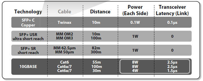
10GE (10 Gigabit Ethernet) is the network of choice for I/O consolidation. Fiber continues to be used for longer distances, but copper is deployed in the data center to reduce the costs. Unfortunately, due to the complexity of encoding and decoding 10GE traffic onto and from a copper twisted pair (IEEE 10GBASE-T) and significant power requirement a more practical solution pop up in the data center. At the rack level, is to use SFP+ with Copper Twinax cable (defined in Annex of SFF-8431). This cable is very flexible; approximately 6 mm (1/4 of an inch) in diameter, and it uses the SFP+ as the connectors. Twinax cables are low cost, use little power, and introduce negligible delay. Copper Twinax cables are limited to 10 meters (33 feet) that is sufficient to connect a few racks of servers to a common top of the rack switch.
Lossless Ethernet
To satisfy the requirements of Unified Fabric, Ethernet has been enhanced to operate both as a “lossless” and “lossy” network. This classification does not consider the fact that Ethernet can still lose frames due to transmission errors, but in a controlled environment, such as a data center, where links are limited in length, these loses are extremely rare.
Avoiding frame drops is mandatory for carrying block storage traffic over Ethernet, since storage traffic does not tolerate frame loss. SCSI was designed with the assumption that SCSI transactions are expected to succeed and that failures are so rare that is acceptable to recover slowly in such an event. Fibre Channel and InfiniBand are examples of lossless technology.
PFC (Priority-Based Flow Control)
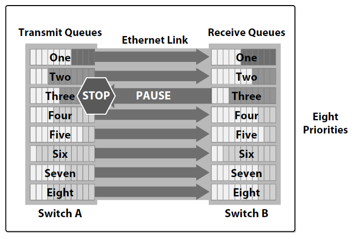
Following these requirements, Ethernet has been enhanced by IEEE 802.1Qbb (priority-based flow control) and IEEE 802.3bd (frame format for priority-based flow control). According to these new standards, a physical link can be partitioned into multiple logical links (by extending the IEEE 802.1Q priority concept) and each priority can be configured to have either a lossless or a lossy behavior. This new mechanism was also previously known as PPP (Per Priority Pause).
With PFC, an administrator can define which priorities are lossless and which are lossy. The network devices will treat the lossy priorities as in classical Ethernet and will use a per priority pause mechanism to guarantee that no frames are lost on the lossless priorities.
PFC requires a more complex organization in the data plane that allows for resources, such as buffers or queues, to be allocated on a per-priority basis. PFC is the basic technique required to implement I/O consolidation. Additional techniques make I/O consolidation deployable on a larger scale. The next paragraphs describe two additional components:
- Discovery Protocol (DCBX);
- Bandwidth Manager (ETS: Enhanced Transmission Selection).
DCBX: Data Center Bridging eXchange
DCBX is a discovery and configuration protocol that guarantees that both ends of an Ethernet link are configured consistently. DCBX works to configure correctly switch to switch links and switch to host links. This is to avoid “soft errors” that can be very difficult to troubleshoot. DCBX discovers the capabilities of the two peers at each end of a link: It can check for consistency, it can notify the device manager in the case of configuration mismatches, and it can provide basic confi guration in the case where one of the two peers is not confi gured. DCBX can be configured to send conflict alarms to the appropriate management stations.
Bandwidth Management
IEEE has standardized a hardware efficient scheduler (two-level DWRR with strict priority support) in IEEE 802.1Qaz ETS (Enhanced Transmission Selection). With this structure, it is possible to assign bandwidth based on traffic classes, for example: 40% LAN, 40% SAN, and 20% IPC. This architecture allows control not only of bandwidth, but also of latency. Latency is becoming increasingly important for IPC applications.
FCoE (Fibre Channel over Ethernet)
FCoE, being based on the FC protocol dominant in storage networks, is able to provide a true I/O consolidation solution based on Ethernet. The idea behind FCoE is simple—to implement I/O consolidation by carrying each FC frame inside an Ethernet frame. The encapsulation is done on a frame by frame basis and therefore keeps the FCoE layer stateless and it does not require fragmentation and reassembly. FCoE traffi c shares the physical Ethernet links with other traffic, but it is run on a lossless priority to match the lossless behavior guaranteed in Fibre Channel by buffer-to-buffer credits.
FCoE has the advantage of being completely part of the Fibre Channel architecture and it is therefore able to provide seamless integration with existing FC SANs, allowing reuse of existing FC SAN tools and management constructs.
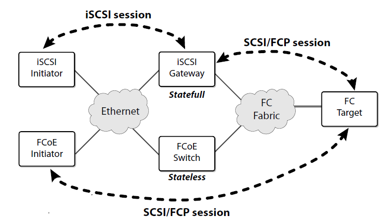
Another notable advantage of FCoE is that it requires no gateway. In fact, the encapsulation/decapsulation functions simply add or remove an Ethernet envelope around a FC frame. The FC frame remains untouched and the operation is stateless.
The management tools that customers use to manage and maintain their SANs today can be used in an FCoE environment. From a storage administrator perspective, zoning is a basic provisioning function that is used to give hosts access to storage. FCoE switches provide the same unmodifi ed zoning functionality ensuring that storage allocation and security mechanisms are unaffected. The same consideration applies to all other Fibre Channel services, such as dNS, RSCN, and FSPF.
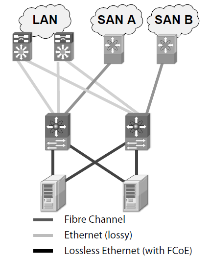
In FC, all the links are point-to-point, while Ethernet switches creates multi-access network. Figure below shows a classical blade server deployment where two Ethernet switches inside the blade server create two “Ethernet clouds (its not the cloud but just classical ethernet network)” to which multiple FCoE capable end stations are connected. It is therefore necessary to discover among the end stations connected to a cloud that are FCoE capable. For this reason, FCoE is really two different protocols:
- FCoE itself is the data plane protocol. It is used to carry most of the FC frames and all the SCSI traffic. This is data intensive and typically it is switched in hardware.
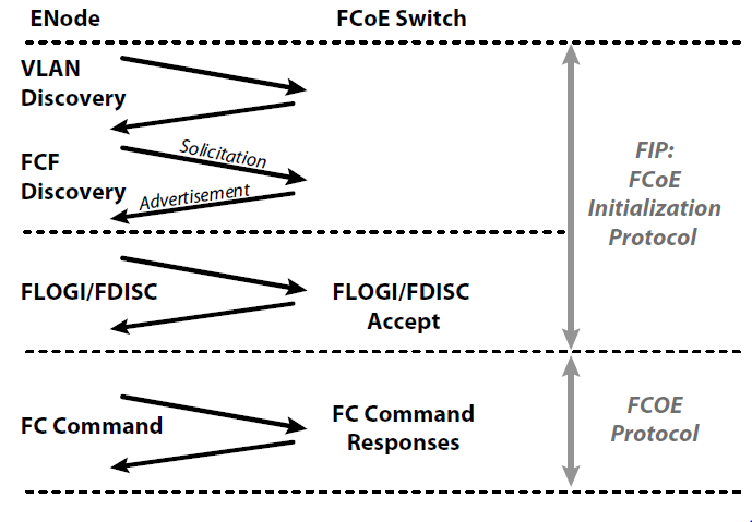
- FIP (FCoE Initialization Protocol) is the control plane protocol. It is used to discover the FC entities connected to an Ethernet cloud and by the hosts to login to and logout from the FC fabric. This is not a data intensive protocol and it is typically implemented in software on the switch supervisor processor.

The two protocols have two different Ethertypes. Figure below shows the steps of FIP that lead to a successful FLOGI and to the possibility of exchanging SCSI traffic using FCoE.
Once the initialization phase is completed, virtual ports are created. The term “virtual” refers to an FC port that is implemented on a network that is not native FC. Therefore, FC-BB-5 defines:
- VN_Port (Virtual N _Port): An N _Port over an Ethernet link
- VF_Port (Virtual F _Port): An F _Port over an Ethernet link
- VE_Port (Virtual E_Port): An E_Port over an Ethernet link
The CNA deployed is seen in the server like two physical adapters. One classical ethernet and one HBA. Of course with VIC adapter this can be tweaked and many adapters can be logically created from one CNA. I just wanted to emphasize that one CE adapter is seen as both the FC and CE.