Modern processors or CPUs (Central Processing Units) are built using the latest silicon technology and pack millions of transistors and megabytes of memory on a single die (blocks of semiconducting material that contains a processor). Multiple dies are fabricated together in a silicon wafer; each die is cut out individually, tested, and assembled in a ceramic package. This involves mounting the die, connecting the die pads to the pins on the package, and sealing the die. At this point, the processor in its package is ready to be sold and mounted on servers.

Sockets
Processors are installed on the motherboard using a mounting/interconnection structure known as a “socket.” This allows the customers to personalize a server motherboard by installing processors with different clock speeds and power consumption, The number of sockets present on a server motherboard determines how many processors can be installed. Originally, servers had a single socket, but more recently, to increase server performance, 2-, 4-, and 8-socket servers have appeared on the market.
In the evolution of processor architecture, for a long period, performance improvements were strictly related to clock frequency increases. The higher the clock frequency, the shorter the time it takes to make a computation, and therefore the higher the performance. However these times the frequency reached physical limitation and there are other means how to improve performance of CPUs like multiple COREs per CPU, multithreading, etc.
Cores
Multi-core processors are now common in the market. Each processor (aka socket) contains multiple CPU cores (2, 4, 6, and 8 are typical numbers). Each core is associated with a level 1 (L1) cache. Caches are small fast memories used to reduce the average time to access the main memory. The cores generally share a larger level 2 (L2) or level 3 (L3) cache, the bus interface, and the external die connections.
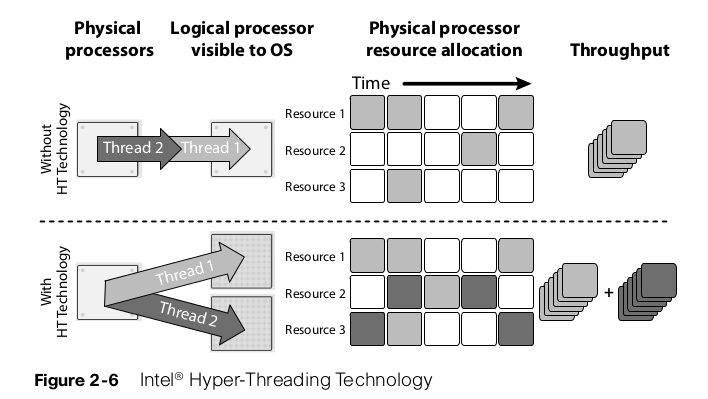
Threads
Processes can be single-threaded or multi-threaded. A process that is single thread process can execute in only one core and is limited by the performance of that core. A multi-threaded process can execute on multiple cores at the same time, and therefore its performance can exceed the performance of a single core. Intel® Hyper-Threading Technology allows two threads on the same core at the same time. Each core has multiple execution units capable of working in parallel, and it is rare that a single thread will keep all the resources busy.
Cache-Hierarchy
The requirement of an ideal memory system is that it should have infinite capacity, infinite bandwidth, and zero latency. Of course, nobody knows how to build such a system. The best approximation is a hierarchy of memory subsystems that go from larger and slower to smaller and faster. In Nehalem, Intel® added one level of hierarchy by increasing the cache layers from two to three. Level one caches (L1) (Instruction and Data) are unchanged compared to previous Intel® designs. In the previous Intel® design, the level two caches (L2) were shared across the cores. This was possible since the number of cores was limited to two. Nehalem increments the number of cores to four or eight, and the L2 caches cannot be shared any longer, due to the increase in bandwidth and arbitration requests (potentially 8X). For this reason, in Nehalem Intel® added L2 caches (Instruction and Data) dedicated to each core to reduce the bandwidth toward the shared caches that is now a level three (L3) cache.
Intel Virtualization Support
Intel® Virtualization Technology (VT) extends the core platform architecture to better support virtualization software e.g., VMs (Virtual Machines) and hypervisors. It does this by implementing new instruction sets into the CPU, I/O adapters, chipset structure and accelerating everything. Without it the virtualization would not be possible due to lack of performance.
VT has four major components:
- Intel® VT-x refers to all the hardware assists for virtualization in Intel® 64 and IA32 processors. VT-x is the technology that enables the virtualization on CPU itself = it enables the hardware support for virtualization. If there is software such as VMware that enables virtualization, why implement Virtualization Technology inside the CPU? The advantage is that CPUs with Virtualization Technology have some new instructions to control virtualization. With them, controlling software (called VMM, Virtual Machine Monitor) can be simpler, thus improving performance compared to software-based solutions. When the CPU has support to Virtualization Technology, the virtualization is said to be hardware-based or hardware-assisted. This is like implementing specialized ASIC for this task – thus accelerating all the things.
- Intel® VT-d for Directed I/O (Intel® VT-d) refers to all the hardware assists for virtualization in Intel chipset. In addition to the virtualization support provided inside CPU, other improvements have been implemented at the chipset/motherboard level to better support.
- Intel® VT-c for Connectivity (Intel® VT-c) refers to all the hardware assists for virtualization in Intel networking and I/O devices. Intel® Virtualization Technology for Connectivity (Intel® VT-c) is a collection of I/O virtualization technologies that enables lower CPU utilization, reduced system latency, and improved networking and I/O throughput. The VT-c consist of Virtual Machine Device Queues (VMDq) and Virtual Machine Direct Connect (VMDc). In virtual environments, the hypervisor manages network I/O activities for all the VMs (Virtual Machines). With the constant increase in the number of VMs, the I/O load increases and the hypervisor requires more CPU cycles to sort data packets in network interface queues and route them to the correct VM, reducing CPU capacity available for applications. Intel® Virtual Machine Device Queues (VMDq) reduces the burden on the hypervisor while improving network I/O by adding hardware support in the chipset. In particular, multiple network interface queues and sorting intelligence are added to the NIC. Virtual Machine Direct Connect (VMDc) enables direct networking I/O assignment to individual virtual machines (VMs). This capability improves overall networking performance and data isolation among VMs and enables live VM migration. Dividing physical devices into multiple VFs allows physical I/O devices to deliver near-native I/O performance for VMs. This capability can increase the number of VMs supported per physical host, driving up server consolidation.
- NetQueue® to take full advantage of VMDq, the VMMs (hypervisor) needs to be modified to support one queue per Virtual Machine. For example, VMware® has introduced in its hypervisor a feature called NetQueue that takes advantage of the frame, sorting capability of VMDq. The combination of NetQueue and VMDq offloads the work that ESX has to do to route packets to virtual machines; therefore, it frees up CPU and reduces latency
- VT Flex Migration to simplify Virtual Machine movement allowing migration of the VM between processors that have a different instruction set. It does that by synchronizing the minimum level of the instruction set supported by all the processors in a pool. This is very cool feature as compilation is needed for application to run on specific processor. Programs called compilators are compiling the source code to specific CPU instruction set (as different cpu can support different functions etc.) As you install specific OS/Application on specific HW, this OS/Application is not then transferable to different HW.
Front-side Bus
In the presence of multi-sockets and multi-cores, it is important to understand how the memory is accessed and how communication between two different cores work. In modern processors, this is a 64-bit wide bus that is operated at 4X the bus clock speed. The FSB is connected to all the processors and to the chipset called the North-bridge. The Northbridge connects the memory that is shared across all the processors.
One of the advantages of this architecture is that each processor has knowledge of all the memory accesses of all the other processors in the system. Each processor can implement a cache coherency algorithm to keep its internal caches in synch with the external memory and with the caches of all other processors. The CPUs have to have its cache in sync because in current multi-core and multi-thread environment one application can be served by different cores/threads. Platforms designed in this manner have to contend with the shared nature of the bus. As FSB is shared resource the CPUs has to content for the resource which may results congestion.
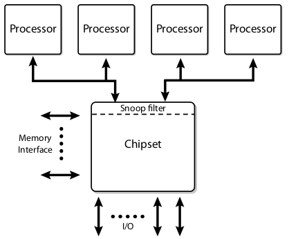
Note: Chipset = North Bridge, South Bridge. FSB is shared bus which connects the CPU with North Bridge. Please see the pictures below to understand how is North and South Bridge connected with other components.


Dual Independent Buses
To further increase the bandwidth, the single shared bus evolved into the Dual Independent Buses (DIB) architecture, which essentially doubles the available bandwidth. However, with two buses, all the cache consistency traffic has to be broadcasted on both buses, thus reducing the overall effective bandwidth. To minimize this problem, “snoop filters” are employed in the chipset to reduce the bandwidth loading.
Dedicated High-Speed Interconnects
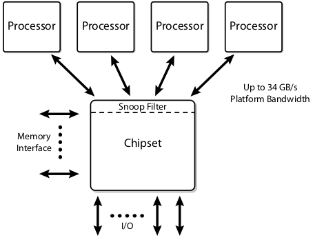
The next step of the evolution is the Dedicated High-Speed Interconnect (DHSI). DHSI-based platforms use four independent FSBs, one for each processor in the platform. Snoop filters are employed to achieve good bandwidth scaling. The FSBs remains electrically the same, but are now used in a point-to-point configuration.
Intel QuickPath Interconnects
With the introduction of the Intel Core i7 processor, a new system architecture has been adopted for many Intel products. This is known as the Intel® QuickPath Interconnect (Intel® QPI). This architecture utilizes multiple high-speed uni-directional links interconnecting the processors and the chipset.
Notice in the picture below that with QPI the Processors are now directly connected via the Integrated Memory Controller into the RAM memories. Processors implementing Intel® QPI also have full access to the memory of every other processor, while maintaining cache coherency.

The Memory Subsystem
The electronic industry has put a significant effort into manufacturing memory subsystems capable of keeping up with the low access time required by modern processors and the high capacity required by today’s applications. Before proceeding with the explanation of current memory subsystems, it is important to introduce a glossary of the most commonly used terms:
- RAM (Random Access Memory) – random means that any type of memory can be accessed in any time. The sequential type of memory (memory tapes) cannot be accessed randomly but in sequential order.
- SRAM (Static RAM) – they use more transistors to store data. Resulting the less data to be stored than in DRAM. The memory capacitators dont need to be recharged like in DRAM. SRAM are generally faster than DRAM, and much less power greedy as the capacitators dont needs to be refreshed
- DRAM (Dynamic RAM) – DRAMs (Dynamic RAMs) are the only choice for servers. The term “dynamic” indicates that the information is stored on capacitors within an integrated circuit. Since capacitors discharge over time, due to leakage currents, the capacitors need to be recharged (“refreshed”) periodically to avoid data loss. The memory controller is normally in charge of the refresh operations.
- SDRAM (Synchronous DRAM) – the memory is utilizing synchronous data transfer which results much faster output. Memory is synchronized with the clock signal of the bus.
- SIMM (Single Inline Memory Module) – the type of memory slot
- DIMM (Dual Inline Memory Module) – the type of memory slot
- UDIMM (Unbuffered DIMM) – In UDIMMs, the memory chips are directly connected to the address and control buses, without any intermediate component.
- RDIMM (Registered DIMM) – RDIMM have additional components (registers) placed between the incoming address and control buses and the SDRAM components. These registers add one clock cycle of delay but they reduce the electrical load on the memory controller and allow more DIMM to be installed per memory controller. RDIMMs are more expensive and are found mostly on servers because of the scalability potential.
- DDR (Double Data Rate SDRAM) – using much higher clock signal
- DDR2 (Second Generation DDR) – using much higher clock signal
- DDR3 (Third Generation DDR) – using much higher clock signal
The I/O Subsystem
The I/O subsystem is in charge of moving data from the server memory to the external world and vice versa. Historically this has been accomplished by providing in the server motherboards I/O buses compatible with the PCI (Peripheral Component Interconnect) standard. PCI was developed to interconnect peripheral devices to a computer system, it has been around for many years and its current incarnation is called PCI-Express. The Peripheral Component Interconnect Special Interest Group (PCI-SIG) is in charge of the development and enhancement of the PCI standard.
PCIe (PCI Express) removes one of the limitations that have plagued all the I/O consolidation attempts—i.e., the lack of I/O bandwidth in the server buses. It is supported by all current operating systems. PCIe can be deployed in different size. It can be for example PCIeX1, PCIeX16. The „X“ refers to number of lanes the card has. The more lanes, the bigger transfer speed. Current PCIe standard is 3.0 which increase the bandwidth around 3 times than PCIe 1.0.
In Cisco UCS or any other Blade system you may come to term „mezzanine card“. What it is? Blade servers are very small comparing to regular rack mount servers. The normal PCI cards are too big to fit into Blade Server. Thats why the network adapters called mezzanine cards are connected to mezzanine port on Blade Servers to solve this issue. Mezzanine ports is completely different port. This card has been constructed in a way that fits to the Blade server. The term mezzanine is widely used by most vendors and refers to the physical way it ‘stacks’ onto the motherboard like a mezzanine level in a physical building. Mezzanine cards are used on blades servers.